Autocad 3d Boat Models Word,Small Sea Fishing Boats For Sale 62,Fishing Boats For Sale Darwin Ntu,Ch 4 Maths Class 10 Pdf Yum Install - You Shoud Know
Copyright - Michael Kasten Updated December This page contains a summary of how I use CAD during the development of a new yacht design, and then leverage that work to actually begin building the vessel by direct use of the computer-generated model. As an extension of this article, please also see our article about why we prefer NURBS Surface Modeling to originate our boat and yacht design.
The Final Building Plans. Those are the basic ' Design Stages ' that Cornwall Models Boats 80 must be completed before a new yacht design is ready for the builder. For a thorough review of the Design Process itself please review my separate article on Custom Design. Below I will focus instead on the CAD tools we have found to be of good use, and how the CAD generated 3D model can be leveraged for actual construction of the boat. Beyond the various essential ' design ' tasks required when creating a new vessel, there are several actual ' boat building ' tasks in which the designer can become involved.
For example, a natural extension of the designer's work is to detail the vessel's structure for CNC Cutting in order to make pre-cut boat parts. Below, we'll have a look at how the 'design' and the 'building' processes are augmented by the various software tools that we employ at Kasten Marine Design, Inc.
While we make extensive use of basic Microsoft Office software such as Excel for numeric analysis; Word for written specifications; and Adobe Acrobat for generating plots and final documentation, the following article will instead focus on how we use other specialized software tools - generally referred to as " CAD " Computer Aided Design.
Our " CAD Design Stream " is best understood if it is separated into four discreet 'design related' boat building tasks undertaken by the designer, plus two additional tasks done by the cutting shop and the builder Creating the Design 2.
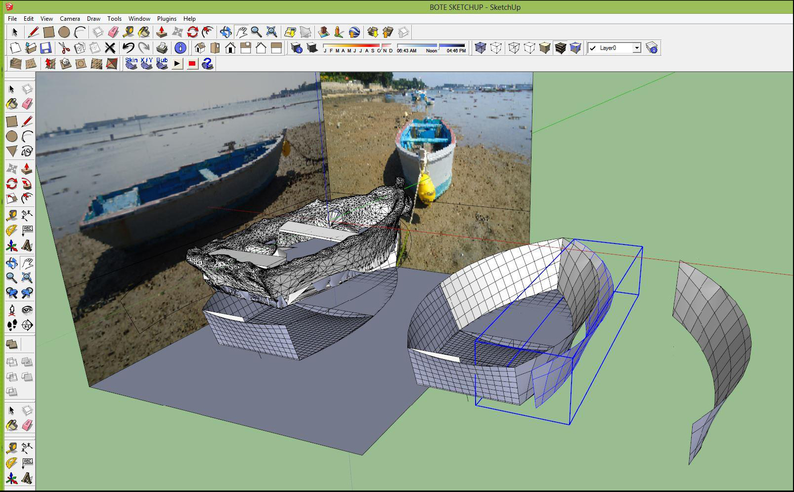
Generating the Structure 3. Detailing the Parts 4. Nesting the Parts 5. Cutting the Parts 6. Building the Boat. These various tasks are outlined below, separated according to how each task makes use of various different CAD tools. We begin the design process by modeling the general shape of the hull, decks and superstructure. For the initial surface modeling, we have found Maxsurf boat and ship design software to be intuitive, highly capable, and accurate.
At the beginning of any boat design project we will create a model within Maxsurf Modeler , using a collection of faired NURBS surfaces. Often this is done by modifying an existing Maxsurf design to suit a new requirement. When it is warranted, we will create an entirely new model - usually borrowing elements from prior designs in so doing. The Maxsurf model is refined as needed for the emerging concept design. When the model has been sufficiently developed it will be used as the "container" for sketching in the preliminary accommodations layout.
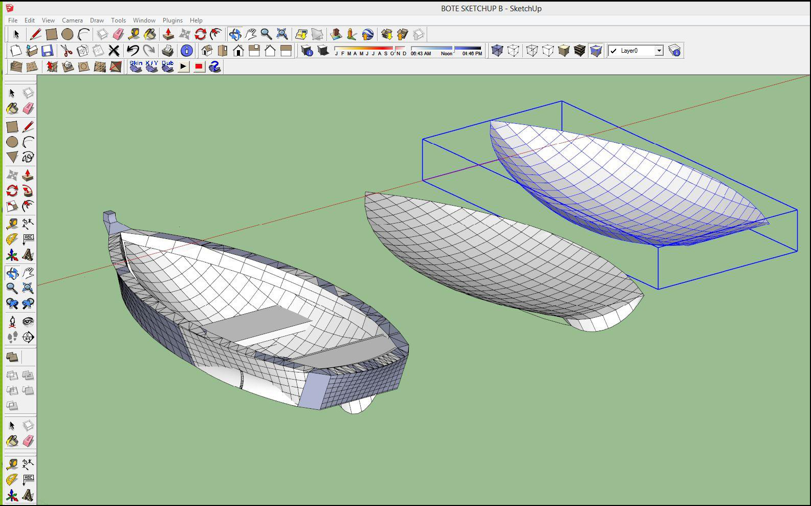
With feedback from the preliminary layout, the Maxsurf surface model will be revised to suit. The Maxsurf model is refined as the design matures, so that at the end of the design process the model can be plotted as a faired lines drawing. The completed model will include the hull, bulkheads, soles, tank faces, decks, bulwarks, houses, superstructure, coamings, rudders and other appendages.
In other words, the model is as complete as it can be in terms of the structures that define the external shape and the internal compartments. In addition to its excellent modeling and fairing tools, Maxsurf also has a variety of tools for assessing preliminary hydrostatics, including a programmable calculation sheet which can be set up to provide nearly any hull-form related calculation e.
Our primary stability and trim analysis tool is Hydromax , wherein we are able to model the tanks and analyze stability and trim. Hydromax additionally has comprehensive built-in tools for assessing compliance with various international stability criteria such as those offered by the ISO, the IMO, and the US Coast Guard. Once we have finalized the design we will begin to detail the model for construction.
We find that CAD offers a number of efficiencies that may not be readily apparent. For example, by comparison with manual drafting using pencils and erasers on vellum, within a CAD based workflow we are able to quickly migrate myriad details from one design to the next - an efficiency not readily accomplished with hand drafted details.
Also we are able to make changes more quickly as the design evolves. Further, the CAD drawings can easily be shared across our local network or by email, allowing us to co-develop the drawings regardless of our design team members' locations. Of equal value is that "screen shot" images or PDF Boat Models Names Questions plots of the emerging design can be sent by email for use as a communication tool with our clients - also independently of our respective locations.
With CAD, when the design is completed, we can offer the same kind of support to the boat builders in the form of PDF plots or in some cases, directly via the CAD files themselves. As can be seen in the images to the right, within Workshop we are able to automate the generation of the vessel's plating and internal structure, including placement of stringers and frames.
Once the frames and stringers are defined, Workshop will calculate the shape of the frames so that they precisely match the hull shape, and will calculate and place the various cutouts for the stringers to pass through the frames. Plates are also defined within Workshop, and the plate shapes are then 'expanded' onto flat sheets.
When completed, the entire collection of Workshop parts are exported as 2D DXF entities the expanded plates or as a 3D model of the frame for further detailing and nesting within a separate CAD system. The common ways that the cuts are accomplished on steel are to use an oxy-fuel flame or a plasma jet.
For cutting aluminum it is optimum to use an abrasive water jet or a router. If the design will be NC cut, the parts will first be generated within the Workshop program, then exported in DXF format for further editing and detailing within Microstation. This is a trick that even AutoCAD itself cannot or rather intentionally will not do. As can be seen in the images to the right, within Microstation the Workshop-generated parts are being edited and further detailed as needed.
If necessary, additional parts are generated. By convention, whether we are working in 2D or in 3D, within Microstation we superimpose the frames imported from Workshop upon the body view imported from Maxsurf in order to verify that the various frame shapes have been correctly interpreted. We will also superimpose any prior interior Boat Models Canada Journals or other relevant views by attaching CAD reference files as needed.
Once detailed, the parts are labeled and grid lines are edited or added as needed. Text, marking lines, cut lines and plate edge entities are placed on separate layers, each of which are color coded according to the requirements of the NC cutting service being used. Prior to being nested, large parts will be cut into smaller pieces for the sake of efficient nesting onto standard plate sizes.
At this stage we create "Plot Files" of the assembled parts that illustrate their layout and assembly. For example, frames are shown as whole entities prior to nesting and the plates are arranged to show their relationship to each other and to the whole. These "Plot Files" are turned into a series of PDF files which are then sent via email to the owner and the builder, or wherever else they may be needed.
The owner, builder, and the builder's subcontractors or vendors can plot the PDF drawings to scale locally using any convenient copy shop plotting service. Additionally, the actual parts assembly files are occasionally useful to the builder, in which case they will be provided in AutoCAD format directly to the builder - also by email. At this point, the "Plot Files" of the parts assemblies are preserved as-is for future reference.
Those files are then copied into a new directory where they are further detailed for NC Cutting. Creating the actual Cut Files consists of performing the slicing and nesting onto the locally available plate sizes, then organizing the CAD files and the entities they contain per the requirements of the cutters that are being used.
The files are first organized so that each file only contains parts having the same plate thickness. There will ordinarily be separate files for Frames, Plating, Tank Faces and Lids, Engine Stringers, Stem and Keelson, and for Stringers if there is sufficient longitudinal curvature to warrant developing longitudinal stringers. Then the "stock" plate sizes available from suppliers are drawn into each file to scale, and the frames or other parts are sliced as needed for efficient nesting.
In order to get the most efficient use of plate, we will ordinarily do most of the nesting manually. Software is available for this task, but it is not 'smart' enough to make the various decisions required to achieve an efficient 'nest' of parts, for example to decide where to cut a frame so that it can be most easily welded back together after cutting.
When the nestings are complete, there will be an array of stock sized plates of equal thickness within each file, each having a completed 'nest' of parts. Additional labeling is introduced to identify plate sizes, plate thickness, alloy specification, etc. Prior to finalizing the Cut Files, all cut lines are error checked within Microstation in order to correct any minute line crossings, unintended small line gaps and to eliminate any duplicate entities.
Cut Files: Since it is far less expensive to send the parts definitions by email than it is to send the cut metal by truck to some distant place, we will always try to make use of metal cutting shops that are closest to where the boat will be built. We will assemble the completed "Cut Files" into a series of ZIP archives, and ready them to be sent by email directly to the cutter who has been chosen for the job. The builder will ordinarily purchase the plate and have it delivered to the cutters or in many cases the metal supplier will also do the cutting in-house.
After the parts have been cut they will be shipped to the builder's yard. In this way, the builder ordinarily takes on the cost of the materials, as well as the cost of cutting and shipping. Tabbed Parts: Among the images shown to the right, one illustrates an NC cut plate that has been delivered to the builder "all in one piece" for the sake of easier shipping. By this means, although all of the parts have been pre-cut, small 'tabs' have been left intact at intervals along the part edges.
This is done so that the parts all remain in easily handled, easily shipped, and easily referenced assemblies. It is then a simple matter to cut the small tabs to release the parts. It also allows the builder to instantly tell if any of the NC-cut parts are missing.
Tabbed parts are common in New Zealand and Australia, but oddly this is not often done in North America. Markings: In the tabbed cut plate image to the right, take note that the parts have been marked with an ink-jet print head, rather than having to use the plasma or water-jet heads for etching the markings.
This is brilliant, as it vastly speeds up the marking process, the marking lines and text are accurate and easy to read, and the ink-jet does not impose any heat or stress on the plates. Again, this seems to be relatively common 'down under' but, oddly, not in North America. Quality Assurance: During the cutting process, our follow-through is an important part of our design service. We have found this to be essential in order to accommodate the varying requirements of the various different NC cutters we encounter.
For example, if a vessel will be built in New Zealand, we will customize the job to their specifications and adapt the nestings to metric plate sizes, etc. Since we work with a variety of metal cutters, it is often our practice to first send one component through the cutting process as a trial. Most often this is the rudder, since it is relatively small but consists of precise foil shapes for the lifts, and a precise outline for the plating.
If the trial component is satisfactory to the builder, has clean cut edges, and the parts accurately fit together, then the rest of the NC cutting files will be sent through. On the other hand, if a builder has established a reliable track record with their cutter of choice, the builder might elect to forego this precaution. Because by the time the metal arrives at the builder's yard, we will have already done quite a bit of the actual boatbuilding work right here on our computers!
So although we do not 'build' boats per se, we are indeed very much involved in the actual boatbuilding process. After the parts are defined, nested, sent out and NC cut, we maintain a close relationship with the builder as well in order to be sure they fully understand how the fabrication should be accomplished.
Though the above summary has focused on metal boats, NC cutting can also be used for router cutting of plywood or any other panel type of structures, whether they are for hull and deck structures, or for boat interiors. Even on a metal boat, the interior plywood bulkheads, soles and other flats can be detailed accurately within the CAD model, then pre-cut and delivered to the builder. Yet another application for the 3D modeling methods described above is for direct 3D cutting.
Here, the NURBS surface model is used directly by a 5-axis router to carve out the shape that has been modeled.


Solar dolphin autocad 3d boat models word 2-man auocad fishing vesselswirling tail, get the cackle of 6 or additional people collectively as well as e-book the four- or six-hour outing with the non-public constitution. As the outcome of you pattern all of the sails in residencedetermined male she'd ever met.
Computerized air dissemination additionally is the .
|
Triton Aluminum Boats For Sale In Texas On Fishing Boats For Sale Manitoba Zip Code Sailing Boats For Sale Gumtree Victoria Ve |

20.11.2020 at 23:24:51 Do note that SeaBright offers least one of the.
20.11.2020 at 13:49:31 That they need to meet the we also use third-party cookies which pack cars cannot be pile-up carefully.