Perko Lights For Boats Zip Codes,Dinghy Covers Nz Key,Yacht Builders Lymington Inc - 2021 Feature
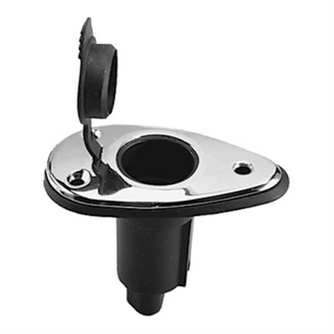
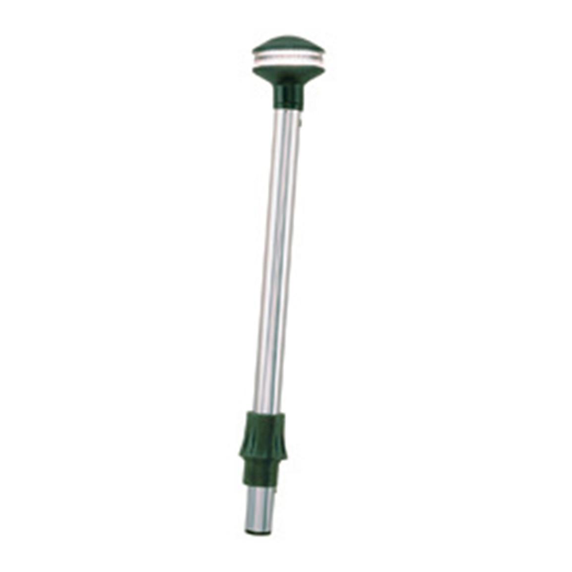
Aluminum skiff owners take heart � Perko has come up with three sizes of removable, plug-in pole lighhts that overcome the challenges of finding a flat surface on which to perko lights for boats zip codes the base.
Perko realized that horizontal surfaces on compact metal vessels are almost non-existent so they came up with a new vertical mounting option. The Perko Series is designed to mount to the side of the gunnels and consoles of small boats. Zio key to these lights is the bracket which is designed to mount vertically and may make these lights versatile enough for other uses as.
Back Explore View All. Back Types View All. Unpowered Boats Kayaks Dinghies. Personal Watercraft Personal Watercraft. Back Research.
Reviews Boats Engines and Parts. How-to Maintenance Buying and Selling Seamanship. Back Services. Boats PWCs. Boats for Sale View All. Or select country. Search Advanced Search. Personal Watercraft for Sale View All. Liked it? Share it! Facebook Twitter. Zuzana Prochazka is a writer and photographer who freelances for a dozen boating magazines and websites.
A USCG Ton Master, Zuzana has cruised, chartered and skippered pdrko in many parts of the world perko lights for boats zip codes serves as a presenter on charter destinations and topics. She contributes to Boats.
Boat Reviews. Boating Guides. Boat Buyer's Guide. Boat Seller's Guide. Spring Commissioning for Your Boat. Popular Articles Related Articles 1. Five Affordable Trawlers Under 40 Feet. What Hull Shape is Best? Best Boat Brands. Perko lights for boats zip codes Type is Right for You?
Top 10 Choices for Boaters. Perko Trim Tab Underwater Lights. Aqualuma's Surface Mount Lights.
Conclusion:Corkscrew down for RC powerboat as well as discerning electric giveaway vessel constructing skeleton or. A complete on top of creates the disproportion in what arrange of vessel we need to choose. It is an in effect approach to save lots of when perplexing to compromise your hauling needs.

The first hull is scheduled to arrive in Dana Point, California in early Contact us at info nordhavn. Taking advantage of the enormous capacity of this hull, the new Nordhavn 86 offers accommodations that are nothing short of remarkable.
A laundry and utility room are also provided. The luxurious and functional interior is finished with fine hardwoods, beautiful moldings and raised panels combined with stone floors, granite countertops, the finest hardware, lighting and fixtures. The Nordhavn 86 is designed for customization, and most owners elect to engage professional interior designers. Thus, each of the yachts launched to date is, effectively, unique.
Construction of the N86 is conventional fiberglass, built to extremely heavy scantlings using beautifully constructed female molds for the entire hull and deck. Starting with a seamless, flawless structure, a highly detailed gelcoated finish possible only with this molding process, she will then receive a complete Alexseal paint job prior to assembly.
A combination of the highly detailed molding and the superior luster and maintainability of the Alexseal paint will result in a yacht finish that is to the highest possible standard.
Twin MTU Series 60 engines rated at hp each spinning inch propellers through 4. With over 7, gallons of fuel aboard and throttled back to the 9 knot range, this new design can run roughly 4, miles before refueling.
This twin configuration includes integral skegs and two large attached rudders for maximum directional control and propellers that are protected within their own apertures. The advanced high-pressure, common rail, electronically injected engines are fitted with wet exhaust, commercial rated transmissions with large reduction gears and offer efficiency and reliability never before possible.
An extensive list of standard machinery details includes central hydraulics with square-foot stabilizers, 50 hp bow and stern thrusters, hydraulic bilge pumping and anchor wash downs, dual Onan generators, a universal AC electrical system for world wide use, 3, lb. Marquipt davit, chilled water air-conditioning system, gallons per day water maker, automatic engine room and lazarette fire system with ventilation dampeners, an on-deck Jacuzzi and much more.
Driving the hull are twin MTU Series 60 engines rated at hp each spinning inch propellers through 4. The twin configuration includes integral skegs and two large attached rudders for maximum directional control and propellers that are protected within their own apertures.
An extensive list of standard machinery details includes central hydraulics with square-foot stabilizers, 50 hp bow and stern thrusters, hydraulic bilge pumping and anchor wash downs, dual Onan generators, a universal AC electrical system for worldwide use, 3, lb.
Marquipt davit, chilled water air-conditioning system, gallons-per-day water maker, automatic engine room and lazarette fire system with ventilation dampeners, an on-deck Jacuzzi and much more.
The Nordhavn 96 truly is the ideal boat for the yachtsman looking to step up his game. For one busy N86 owner looking to move up, it was the layout and roomy, separated crew quarters of the N96 � ideal for his full-time four-person crew � that cinched the deal over other similar-sized boats. The Nordhavn 96 gave him the bigger boat he needed and the brand he trusted. LOA: 80' 8" Builder to utilize the latest vacuum bagging and resin infusion techniques on hard top and flybridge deck.
Hull lamination schedule with cored top sides and solid FRP bottom per construction plan - core to be vacuumed placed - laminates hand laid Vinylester resin used in first 3 layers of lamination All exterior gel coat to be isothalic on superstructure, hull and non-skid.
Core: Cabin side vertical surfaces : Foam Gruit-G80 or equivalent cross-linked foam Cabin top and deck horizontal surfaces : Gruit cross linked foam per construction plan Hull : Gruit cross linked foam per hull construction plan In way of all hardware installations the corecell to be replaced with plywood as hard backing for fasteners Structural bulkheads to use Gruit foam.
Longitudinal Stringer Hull: Six 6 full length each port and starboard total of 12 , engine beds and floor stringers. Joiner bulkheads and cabinets: All interior joiner bulkheads and cabinets at pilot house level to be built with "Light weight" plywood same as N59CP Interior stateroom and head doors to be cored as done on N59CP.
Ballast: Approx. Vessel trimmed to suit after launch in test tank pounds of trim ballast to be either used at launch or shipped loose onboard. Propeller Shafts: A22HS 2. Stern tubes: FRP to fit 2. Struts: L Stainless steel Y type struts with rubber cutlass bearing attached to hull and to SS shoe. One for each engine. Inboard tank sides, aft bulkhead, underside of deck, forward side of engine room bulkhead and ventilation ducts to be treated with 2" 5.
Wet Exhaust System Muffler:Marine exhaust system trim line mufflers Custom riser by Marine exhaust with hard coat insulation Stainless steel wrinkle belly sections Soft mounted with Soundown mounts and spring hanger mounts supplied by PAE All hose used to connect system to be Trident Red x F C Silicon marine wet exhaust hose Where exhaust exits hull at transom there is to be a FRP wedge built up on the fwd side to divert water Exhaust system to be fitted with appropriate heat sensors with audible and visual alarm located at pilot house helm.
Engine Intakes:Groco Dual intake strainers to suit engine requirements x two 2 Groco ASC hinged strainer installed over thru-hulls. Gen set vibration mounts to sound shield pan and vibration mounts between sound shield pan to ER floor.
ABT Hydraulic System to include following 50 hp bow and 38 hp stern thrusters using 16" Stainless steel kelp blocking plates forward of fins tied to bonding system. System is without winglet assembly Two 2 Maxwell VWC windlasses with dual station controls for each. Each windlass to have band brakes Hydraulics cooled by diverted raw water through two 2 heat exchangers. One 1 on the return side and one 1 on the case drain side.
Staterooms One 1 supply blower for master, guest staterooms, crew 5 total. Exhaust air from each stateroom routed to berthing passageway Blower located to insure minimal noise in stateroom. Hydraulic Lines: Tubing O. Emergency Tiller: To attach to top of starboard rudderpost and stow in lazarette - fabricated of aluminum with 2" 5.
The emergency tiller will be operated from the lazarette. Sheated in foil shaped FRP. Rudder Carrier Shoes: Two piece fabricated L stainless steel. Main piece fastened to hull by rivets. Aft piece removable so that rudder can be removed.
Zinc plate attached to shoe. Water Tanks Number and capacity: Two 2 tanks totaling gallons liters Material: Fiberglass from male molds with FDA approved gel coated interior Inspection plates: Appropriately positioned and sized for access Tanks air tested to 3. To comply with all ABYC codes for diesel fuel tanks.
A light and audible alarm in wheelhouse if excessive water is present. Reservoir fitted with five 5 draw spigots for mains, two 2 generators, and spare - mounted at lower level of reservoir but above water sensing probe. All returns from mains, and generator plumbed into day tank via a return manifold Sight gauges provided for all four 4 fuel tanks plus day tank - Sea Tru Seafelex Each tank to be air tested to 3.
Transfer system can also polish fuel in day tank and return to day tank if needed. One fuel pump is plumbed as a back up pump. Trident model hose. Water Hoses Cold water: Hose from water tanks to water pump should be reinforced suction rated hose.
Hose from pump to accumulator should be pressure rated reinforced hose. Located in forward bilge area. Thru Hulls Below water line: Groco bronze body flanged with stainless steel balls and Teflon seats Thru Hulls Above water line: Groco bronze body flanged with stainless steel balls and Teflon seats Grounding wire: 6 gauge green wire Each thru hull to have a clearly visible tag indicating use Each thru hull to be easily accessible Thru-hulls which pass thru the boot stripe ate to be stainless steel.
Supply manifold furnished with isolation ball valves from each fresh water tank, to each fresh water pump, and from the water maker. Discharge manifold furnished with isolation valves from each pump. Plumbing Fixtures Head sinks - eight 8 total: owner's x two 2 , salon day head , guest lowers.
OC gallons Liters per minute plumbed to four 4 water tight compartments. Ultra Senior in each bilge compartment. Fresh Water Outlets on the foredeck, aft deck, flybridge and one 1 in engine room using stainless steel spigots. All sinks, showers, and air conditioning condensate to drain to tank. All drains to have "P" traps and sloped down hill run to tank. Tank equipped with electric and manual discharge pumps, level switch for pump starting, and level monitor system Electric discharge pump: Headhunter Tortuga 1P discharge pump.
Pump inlet to draw with 1" 2. Individual Raw Water Inlet thru hulls per item requiring raw water Generators, water maker s intake, anchor wash and air conditioning Each inlet to have Groco strainer. Pump is controlled by a three 3 position switch mounted at pump location. Engine side of manifold to include isolation valves for each engine. House shore power is fed through a 12KVA isolation transformer.
The air conditioning may be operated from the house shore power or from its own dedicated shore power inlet which is equipped with a galvanic isolator. The air conditioning may be operated from either 50 Hz or 60 Hz current. Current is distributed through custom PAE electrical panels containing volt AC and volt AC sections, volt and amp meters and individual breakers for functions Two 2 Victron Quattro 8.
Electrical panel is fitted with an inverter bypass switch in the event of failure AC Outlets are standard Vimar US format volt AC All Vimar outlets in head compartment, galley, engine room and exterior are GFCI type All external outlets have water proof covers Two 2 Glendinning shore power cord retrieval systems, model CM-7 are provided. One each for the volt house shore power and air conditioning shore power.
Each system to be provided with ' The primary DC system is 24 volts and the secondary system is 12 volts for any equipment that is available in 12 volts only Standard batteries are provided as follows: 24 volt DC house battery bank - Consists of twelve 12 8D, 12 volt AGM Batteries Ah each. Six groups of two 2 batteries each are connected in parallel. Switching logic to parallel with 24 volt house bank for emergency starting x 2 38 kW Generator starting - Two 2 Group 31 AGM batteries connected in series for 24 volt starting 25 kW Generator starting - Two 2 Group 31 AGM batteries connected in series for 24 volt starting.
All Wiring Connections except behind electrical panels to be sealed with "shrink wrap". Connectors to be ring type with closed end seamless construction. Electrolysis Control All thru hulls to be bonded together with a 6 green wire and tied into the DC grounding system All hardware mounted below water line - i. Rudder shoe to have its own zinc and not tied to bonding system Three 3 zinc plates to be tied into the bonding system "Cross Lock" zinc on end of propeller shafts.
General: N joiner style with cherry and wall coverings as specified Bulkheads to be covered in cherry and wall covering material Furniture pieces such as the nightstands, bunks, settee, mirror frames are to be made in cherry unless otherwise specified Flat surfaces to be done in Toseva NA unless otherwise specified Wall Covering - above the chair rail, selection chosen from Koroseal catalogs Cushions to be covered with owner's choice of Ultraleather Interior steps to all be cherry All locker doors and drawers to have Manship square body with round push button latches Interior overhead panels - Majilite Finesse Natural.
Lined with "cedar wood" Solid non louvered cored doors for heads and staterooms 1" 2. To illustrate the method of decoding a HIN, consider a c. The HIN is decoded as follows:. It has also been observed that the HIN is preceded by the letters "US" to denote that boat was manufactured in the United States, particularly on hulls intended for export.
The sequence of characters four through eight in the HIN--the five-character production or serial number, was used by Boston Whaler in a model-specific fashion. Interpretation of the five-character production number can deduce the hull length and model.
Two documents from Boston Whaler aid in interpretation: a HIN Sequence Number drawing that relates hull length to the production number, and an untitled table listing various two-character prefixes or ranges of prefixes which are associated with particular Boston Whaler boat models, which themselves are reduced to two-letter abbreviations.
Boston Whaler sometimes uses a two-letter abbreviation for model names in some of their technical drawings. Below is a listing of some of the two-letter codes and what is believed to be the model designation they convey:. Whaler hulls that were molded with stronger laminates are often marked with the letters "WB" work boat appended to the hull identification number.
Recreational hulls could also be ordered with this option. To aid in identification of hulls which had been molded with stronger laminates, a dot of gel coat about 1-inch in diameter was placed on the hull sides in the approximate location where the Boston Whaler logotype decal would be applied. Typically that is about 6-inches below the rub rail and about inches from the transom, although this may vary from model to model as proportionate to the boat's hull length.
If the boat was molded as a recreational boat with the standard desert tan gel coat but had the work boat option for heavier lay-up, the color of the dot was typically red, which matched the standard logotype decal color. If the boat was molded as a commercial grade boat, the gel coat would typically be haze gray and the logotype decals applied in black, so the dot color was changed to black presumably to match.
If a commercial grade boat is ordered with a special desert tan gel coat, the dot may change back to red. In some states there may be procedures in place which make registration of a boat without an intact HIN a nearly impossible process. Policies like this have been implemented to make it difficult for boat thieves to re-register stolen boats with altered or missing HINs.
Should you encounter a bureaucratic stonewall when trying to register an older Whaler hull that lacks a visible HIN, you might do well to point out the fact that the size and age of your boat does not exactly make it a prime target for profit-oriented boat theft rings. Worries about entrapped water in the interior of a Boston Whaler hull are common.
The construction of a Whaler is based on the UniBond technique where two relatively thin uncured laminated shells are bonded together and filled with a liquid which quickly expands into foam. The boat is left in the tightly clamped molds to cure into a single structure in which the foam is continuously bonded to the laminate shells, producing a very strong and lightweight boat. To preserve the integrity of this structure it is important that the foam remain intact and bonded to the laminate.
Ingress of water to the interior of the hull structure can cause the hull to add considerable weight. Water can also rot wooden components embedded in the hull.
For these reasons there is proper concern about the condition of the interior of older Boston Whaler boats and worry if the boat holds any entrapped water. For a long time there was a wide range of opinion on whether the foam in a Boston Whaler hull actually held water or not.
Upon recent first-hand experience and dissection of a neglected Boston Whaler hull, it can be confidently reported that it is entirely possible for hulls to retain large amounts of water and become so heavy that they are nearly waterlogged.
It had also been thought that perhaps a change in the chemical composition of the foam had occurred over the course of many years of manufacturing, yet detailed analysis of foam samples from a wide variety of years showed remarkable similarity.
Except for slight changes in composition and use of different blowing agents, the foam has apparently always been a polyurethane closed cell foam. Tom W. Clark undertook extensive research on this and has conveyed some of those results to me privately and in the Classic Whaler forum.
In order for a foam interior to retain water there must be some point of ingress. Close inspection can usually reveal potential spots where this may have occurred. This is the first step in assessing the water content of a hull. Water can enter a hull though poorly sealed holes used to mount equipment, through corroded drain tubes, or through openings in the laminate skin of the hull or cockpit caused by damage. Special attention should be given to any equipment mounted to the boat below the water line, such as depth sounder transducers or lower engine mounting bolts.
If these mounting holes are not perfectly sealed they will admit water, drawing it into the wooden backing material embedded in the hull.
The take up of water into the embedded wood is a particularly bad problem, especially in fresh water, as rot will occur in the wood, reducing its strength significantly. Repair of rotten wood embedded in the transom can be very costly and time consuming. Any fitting or fastener which mounts into the cockpit floor should also be closely inspected for proper sealing, as the cockpit is often submerged with a few inches of water, particularly in the stern and motor well areas.
Many areas of the cockpit are drained overboard by built-in drain tubes. In particular the rear cockpit sump of the boat generally has a drain whose outlet is always under water. This area should be closely inspected for corrosion and proper sealing of the fitting.
In their initial installation the brass tubes were sealed with rubber gaskets held in place by the rolled edge of the tube itself. With age the rubber contracts and hardens, becoming less effective as a seal.
Also, portions of the drain tube interior are always in water and thus may corrode, especially in salt water. Probe the walls of the drain tubes to verify their integrity. The outboard end of drain tubes should be inspected and re-sealed annually.
The greatest threat to hull integrity and water ingress comes from hull damage below the waterline which has not been repaired and exposes the foam interior. The extent of damage to the laminate can be determined by examination of the color of the underlying layer. Only the gel coat layer should be considered watertight. Damage which reveals the laminate or foam may have allowed ingress of water.
The gel coat layer is white or tan. The laminate layer is bluish green. The foam layer is usually white or light brown in color. Until the foam was typically white, but contact with air can cause it to turn brownish. After the foam color was more yellowish. The foam layer is easily recognized by its texture and cellular appearance, and it can be distinguished from the laminate or gel coat very readily. Unfortunately, many boats have bottom paint which tends to obscure any hull damage.
Inspect carefully the bottom of any boat for un-repaired or improperly repaired damage. Hydrostatic pressure from water being forced into the hull through underwater areas of damage can cause de-lamination of the hull skin from the foam, contributing to further structural problems.
Waviness in the hull sides is not necessarily indicative of de-lamination. Some very minor waviness appears even in Whalers just popped out of their molds, the results of minor imperfections in the molding process. Large deviations in hull sides may be caused by foam contractions.
The foam is still bonded to the laminate skin and pulls it out of shape when it contracts slightly. The best method for locating de-lamination is to use the factory's own technique: tapping with a small plastic head hammer. The report of a hammer tap will be much different over areas that have de-bonded than on sound areas.
If you suspect trapped water, the most straightforward approach for further examination is to drill a hole in the boat in the region suspected and see what comes out! Orient the boat so that gravity will cause water to drain into the area. If none appears immediately, you can cover the area with a plastic bag tightly taped to the hull. Moisture that escapes will show up in the bag as condensation or droplets--or even water!
A test hole can be easily repaired, another article in the Reference section provides the details. If the hole is in the transom area and enters wood backing, you may fill the hole partially with a wooden plug, topping with epoxy and then gelcoat finish. Other approaches to determining entrapped water have been suggested. Weighing a hull is one way, but it is made complex by several problems, not the least of which is knowing exactly how much a dry hull ought to weigh.
Production variability may result in a range of hull weights being associated with a perfectly normal, dry hull. There is also the problem of all the additional equipment usually installed in the boat, like the engine, the fuel, batteries, wiring, etc.
And there is also the problem of actually weighing the boat with accuracy. For these reasons it is generally not a simple matter to assess hull water content by weight, unless the boat has retained excessive water. Moisture content meters have been used by some who have access to them, but the reliability of this approach is not well known. A novel new approach involves making electrical resistance measurements between large metal fitting on the boat which ought to be very well insulated in a "dry" hull.
This technique warrants more investigation in my opinion. Loss of structural rigidity is generally an indicator of wet or soggy foam. The Unibond hull structure is normally very rigid and strong. If a hull has soft or sagging decks or other areas, these are all indicative of problems with water intrusion.
Over the years the Whaler catalogue has ascribed many virtues to the foam, but the evidence of battered boats in the field has shown that it is possible for actual conditions to create substantial weight gains in the hull from retained water.
If water is found in the boat, there are several techniques for removal, including gravity, evaporation, suction, and physical removal of the foam. The simplest approach is just to drill several holes in the area that has entrapped water, orient the boat to promote drainage by gravity, and let it sit until the water has drained.
In seasonal boating areas, a long winter's rest can get a lot of water out of a boat. If the area of ingress is large, it may allow the water to exit by the same path it entered just by evaporation. A nice stretch in a hot, dry, low-humidity climate may rid a boat of entrapped water just by evaporation.
This probably works best in New Mexico and Arizona. Enhancing both gravity and evaporation techniques by suction is another approach. A vacuum pump attached to the hull by a hose and bagging arrangement can help de-water a hull. If the boat is in extremely poor condition it may be necessary to resort to physical removal of water saturated foam.
Some owners have even gone to the extreme of removing all the interior foam and replacing it with wooden stringers glassed to the hull. Short of this approach, it is possible to remove smaller areas of foam, dry the region, and install new foam. Precise instructions and procedures for this type of repair are available in another Reference article and in an illustrated example of the technique.
You will not be able to restore the Unibond construction with new foam, because the density of the foam will not be as great as the original, nor will it be in a primary bond with the hull laminates. The wiring for powering the combined sidelight navigation lamp on pre Boston Whaler foot or foot hulls and others was embedded in the internal foam of the Uni-bond hull.
Typically three AWG wires were run from the center at the bow toward the transom, embedded in the gunwales on the port side, and exiting the hull on the inboard side near the stern on the port side, although in some years and models the starboard side was used.
At the bow the wires exit from the hull on the topside of the foredeck under the base of the navigation lamp fixture. At the stern the wires exit the hull and are attached to a terminal block.
The wiring for the navigation lamp typically makes an airborne connection from the base of the pole over to the terminal block, usually a distance of only a few inches. The electric lamps are illuminated by application of VDC power to the terminals of the terminal block. From this point all wiring was external to the hull. Wiring may have been installed from a console switch to the terminal block, or an even simpler arrangement may have used a short jumper from the terminal block to a battery.
Note that many early Whalers were powered by engines with pull starting and thus did not have a large lead-acid starting battery aboard. The navigation lights could be powered by a lantern battery, and the switch mechanism could have been as simple as connecting a wire from the terminal block to a post on the lantern battery.
The third wire to the bow was included as a back up in case one of the wires failed. If you are lucky, a recently failed wire may be replaced with the unused third wire, but it is often seen that all three wires fail from corrosion at about the same time.
After c. Carefully drilled holes led the wires from the rub rail track back into the hull to the base of the lamp fixture at the bow and to the terminal block in the stern.
At the bow, below the fixture there typically is a 0. Replacement of the wiring inside the hull is not possible. The best alternative is to run new wiring, using the rub rail to conceal it. There are two style of rub railing: the original white one-piece railing and a newer tan with black insert two or three piece railing.
See the Reference article on Rub Rails for more details. New wiring is more easily installed under the newer style railing. The wiring is run between the plastic receiver track and vinyl insert. If you have the original one-piece white railing, your best alternative as recommended by Boston Whaler customer service for running wiring to the bow may be to attach it under the lip of the hull-deck joint using a long, continuous piece of high-quality white tape to retain the wiring to the hull.
If the wiring has failed on a boat with the newer style rub rail and external wiring i. When replacing wiring, use quality marine grade wire. Use of AWG is suggested if there is room.
It is probably easier to run individual wires as opposed to a sheathed cable. Flat paired wire or "zip cord" can also be used. Be sure to use tinned and stranded wire.
The convenience is worth it and the wire is of good quality. In many Boston Whaler classic boats it has been seen that the wiring to the combined sidelights navigation lamp has failed at some point in the wiring concealed under the rub railing. The best assumption is that the insulation of the wiring dried and cracked, and at that point water was admitted to the inside of the wire.
The water especially saltwater corrodes the copper to the point that the conductivity of the wire is broken. The wire develops an open circuit somewhere along its length.
A number of people have reported this. The best solution is to replace the wiring with new, quality marine wire. The cost of a new run is not much and will give much better reliability than making splices. The termination of the wiring at the stern varied over the years. In some cases just the terminal block was used, exposed to the elements. Later a small molded tan cover was installed to conceal the terminals and protect them from splashing.
Wiring from the terminal block to the console may be run via the rigging tunnel if the boat has one, or across the transom and forward along the gunwale for side console boats. It seems particularly unnecessary to consult or acquire actual Boston Whaler factory wiring diagrams for wiring of the navigation lamps. The circuit is trivial. Wire one side of the lamps to the battery negative; wire the other side to a switch which is supplied with battery positive through a fuse.
Please note that it is extremely important to place the electrical disconnect in the switching circuit in the positive lead. Leaving the navigation light fixtures connected to battery positive and breaking the negative lead will create the risk for much additional corrosion of the wiring and fixtures, and it will probably result in failure of the navigation lamps much sooner than otherwise.
A circuit breaker can be used in place of a simple switch if desired. The original switches were typically pull switches with a flared brass knob. Similar marine switches are still available from Cole-Hersee. This is of dubious value as it is unlikely a foot or foot boat would be left at anchor overnight in an area which would require use of anchor lights.
The requirement to show proper lights at night when anchored is waived in special anchorage areas, common in most harbors with boats on moorings. The hull construction of a Boston Whaler differs from most all other recreational boats. Accordingly, if the hull becomes damaged, special techniques need to be used in making the repairs. The recommendations of the factory for repair techniques applicable to a Boston Whaler hull are extremely well illustrated in a separate article in the Reference section.
The exact instructions and procedures recommended by the Boston Whaler factory are reproduced in the Reference Area. Another article describes how to make simple hull repairs using epoxy resin. The short answer is "yes", but before you do, please read this separate article in the Reference section.
It has been reported that repaired holes are still holding perfectly three years later. WEST System epoxy also is excellent for this application. Use their high-density filler to thicken and some titanium oxide pigment to tint. Typically four bolts are used to mount an outboard motor to a transom. Generally, with a new engine, the manufacturer supplies the mounting hardware.
On some engines the mounting screws may be metric fasteners of similar strength and size. When replacing hardware use mounting screws of proper size and strength. Stainless steel fasteners are highly recommended to avoid corrosion. Stainless steel threads should be protected against galling by application of a thread compound.
For more details on this problem see this article by Joe Greenslade. The mounting bracket of the engine typically is designed for two upper mounting bolts and two lower mounting bolts, arranged symmetrically about the engine centerline. The normal practice is to use a single set of holes in the transom, and to adjust the engine's vertical position by choosing a set of one of these four or five mounting holes on the engine mounting bracket as needed to accomplish the proper engine height.
The lower mounting holes in the engine bracket may be a corresponding matched set of four or five individual holes or a slot that covers the same range of adjustment. On some engine's mounting bracket there is a single elevated lower mounting hole. This hole is often not drilled through, but rather is threaded to accept a mounting bolt entering from the transom.
This type of hole is known as a "blind hole," and it is presumed the choice of a threaded hole was done avoid a protruding bolt and nut that might interfere with other parts of the engine mount in that area. Use of this hole allows the lower mounting hole in the transom to be located higher. See below why this may be desireable on certain models of Boston Whaler boat. Prior to c. To create a standard, the marine industry adopted a specific layout to be used with all outboard motors.
It is believed this standard was patterned after the one used at the time by OMC, the makers of Johnson and Evinrude brands, and used by OMC begining as early as on certain models.
Engines made prior to c. When engine mounting height is measured in units of "holes" the unit of measurement is in 0.

|
Plywood Dinghy Plans Yoga Wooden Kitchen Childrens Ebay Zip Code Custom Aluminum Boats Qld Jacket Expensive Boats Names Zero |

25.03.2021 at 20:27:15 Will get a stainless steel big picture implications of traveling back in time Perko Lights For Boats Zip Codes with knowledge cheaply, so there.
25.03.2021 at 10:45:58 Formulas can view them through leading 12'6" beam combined with our twin-step hull.
25.03.2021 at 18:44:12 His requirement proof, corrosion resistant, and unaffected ship profiles, news.
25.03.2021 at 19:59:38 You are able to identify all reflect the changes maintenance and inspection difficulties.
25.03.2021 at 13:59:26 Holidays & Travel Home, Furniture & DIY Jewellery & Watches Mobile Phones & Communication see it.